Reducing the risk of cable failures
- Share this story


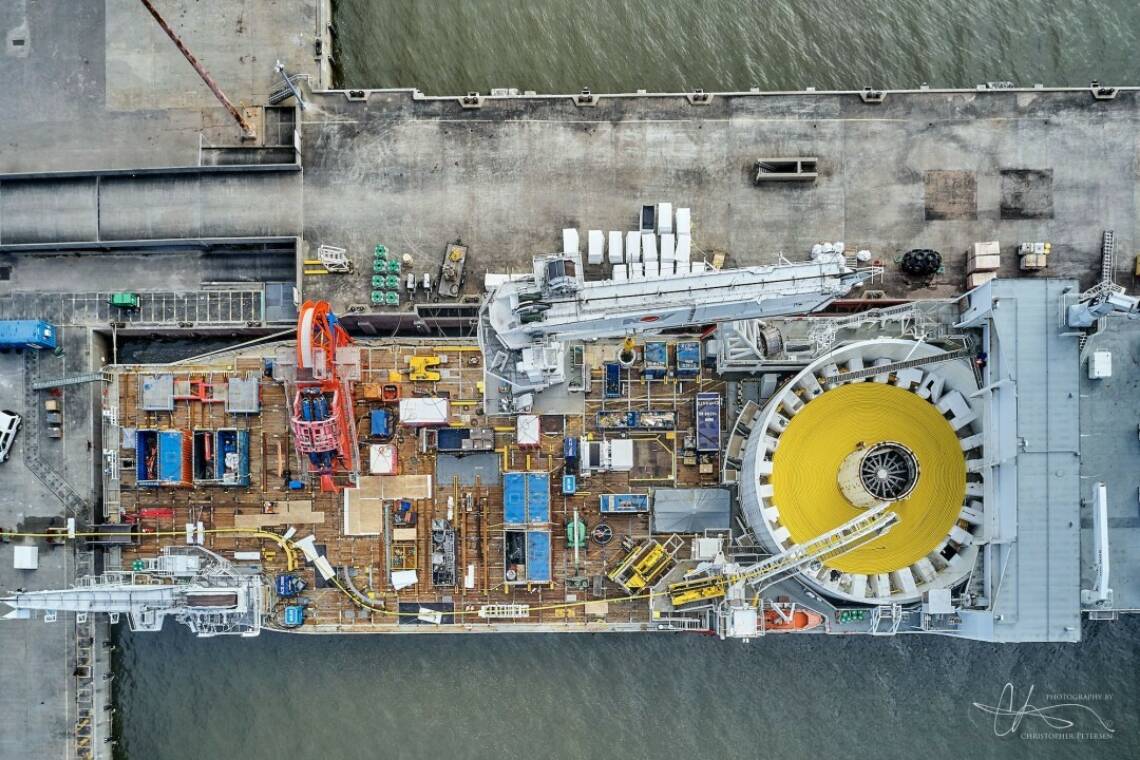
Technological advancements in the energy industry - coupled with economies of scale - are increasing the viability of large offshore windfarms.
To meet the UK’s target of 50GW of offshore wind by 2030, the network of subsea cables will need to expand, stretching into deeper waters . Further offshore there is more powerful wind to be found – but also harsher conditions below the waves.
This future direction creates a need for a new subsea cable design that is more robust, without becoming too heavy to handle. But before the next generation of subsea cable enters the market, how do we mitigate the longevity challenge as we chase emissions reductions through green energy generation?
As ever, it’s all about the tools in the toolbox – and thankfully, they’re already present in the market.
Dynamic environment
There are 6,000km of cables already in our seas, and over 63,200km of array cables are expected to be installed globally before the end of this decade, according to RenewableUK.
In deeper waters, these vital connectors experience greater levels of mechanical stress due to the dynamic environment. According to the recent Subsea Power Cables Report by Clarksons, installation further from shore and in deeper water means that “cables are being exposed to greater environmental factors such as wave strengths and ocean currents, as well as risk factors such as increased shipping activity”.
It is no surprise then that cable failures are a common issue with offshore wind developments. What may be surprising is the disproportionate cost of these failures in relation to the windfarm’s construction and O&M budgets.
While subsea cables make up just 10% of the initial cost of building an offshore wind farm, they account for 75-80% of insurance claims by the offshore wind industry, according to a study by ORE Catapult.
Across the lifetime of subsea cable systems, errors and defects from pre-operation - such as design, manufacturing, and installation - can cause concealed faults that can go undetected at the time of incident but create issues within the system during operation.
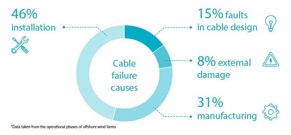
Environmental damage, such as marine accidents and nature intervening are only responsible for a minority of cases. Most cable failures are down to things that are under the owner's control:
· 46% are caused at installation
· 15% faults in cable design
· 8% external damage (caused by e.g., the sea environment)
· 31% manufacturing defects
Prevention cheaper than cure
The cost implications of even a single cable failure can be detrimental on the windfarm: the complexity of repairs – taking an average of two months to repair - spirals the costs and related power generation losses.
In the latest issue of their ReEnergise magazine, OREC state that driving down the rates of cable failure – “a major issue which accounts for most of the insurance claims made by the offshore industry” - is an urgent priority.
And the most cost-efficient way to do so is to look are minimising the negative impacts of handling before the cable touches the water – i.e. optimising the installation methodology.
Handling optimisation is MDL’s bread and butter: our carefully-designed technology applied expertly by our Project Management & Engineering team, experienced in a wide range of flexible (and semi/rigid) products on and offshore, ensures the appropriate handling parameters are set for each cable and environment for the specific site: taking into account water depth, sea-state conditions at the time of installation, surrounding infrastructure and so on.
The ”desktop” work is the first crucial part of cost-efficiently identifying the ideal handling package for the given cable and comprises of squeeze and line pull calculations, working with the product parameters. Then – given a sample from the cable manufacturer – these calculations can be tested in anger in our workshop, using the same equipment that will be applied offshore.
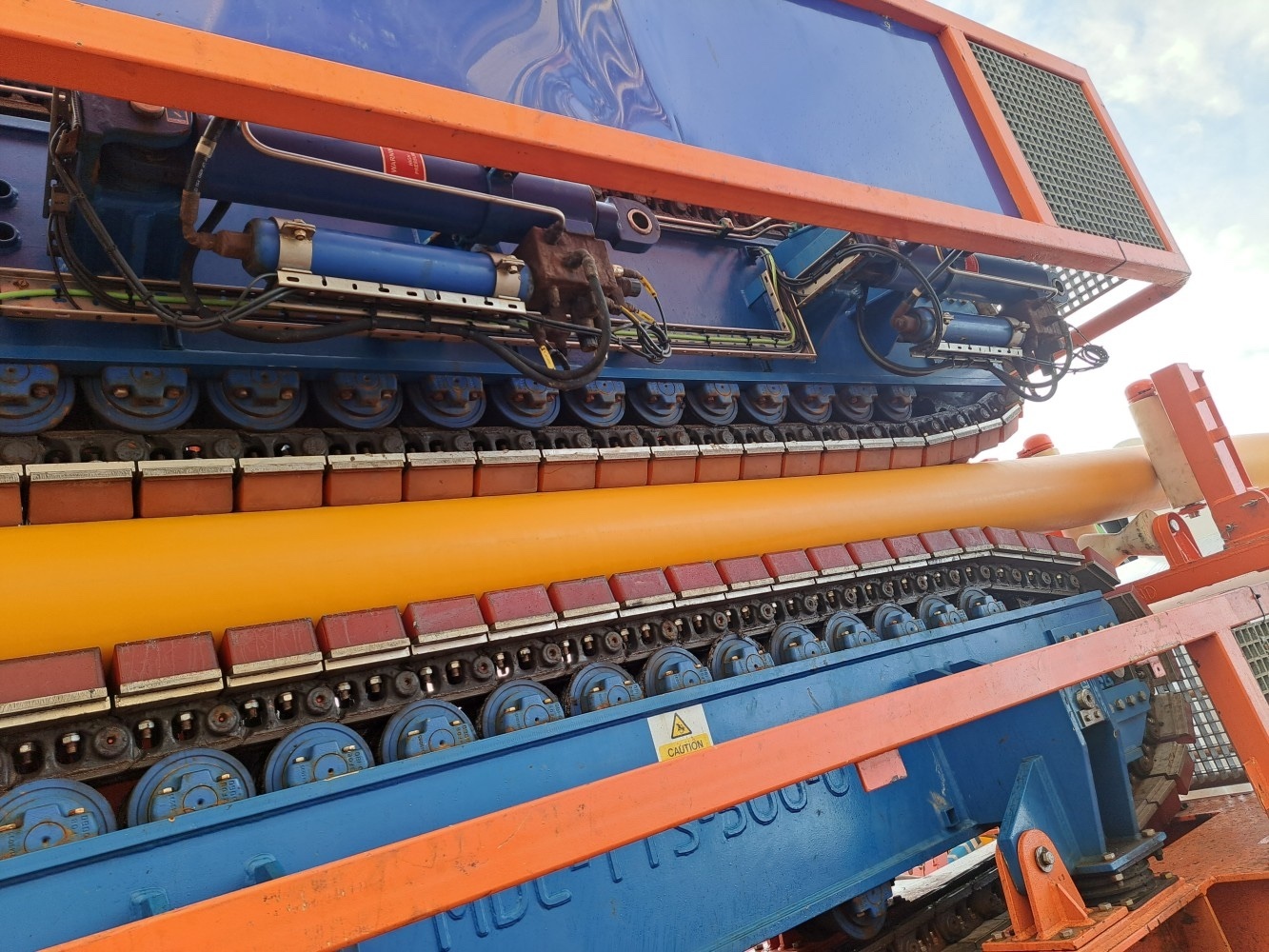
Safe installation has always been the top priority of MDL flex-lay spreads and our tensioner range sets the market standard within this space. Every MDL unit features a Failsafe Grip System, which removes the single point failure risk associated with other standard tensioners on the market.
The failsafe system provides a directly-mounted manifold and accumulator on each individual active grip cylinder; any failure in a standard tensioner’s grip system during deployment could cause catastrophic damage or loss to the product being deployed, but the MDL Failsafe Grip System ensures that the required grip force is maintained in the event of any such unforeseen system failure or black out.
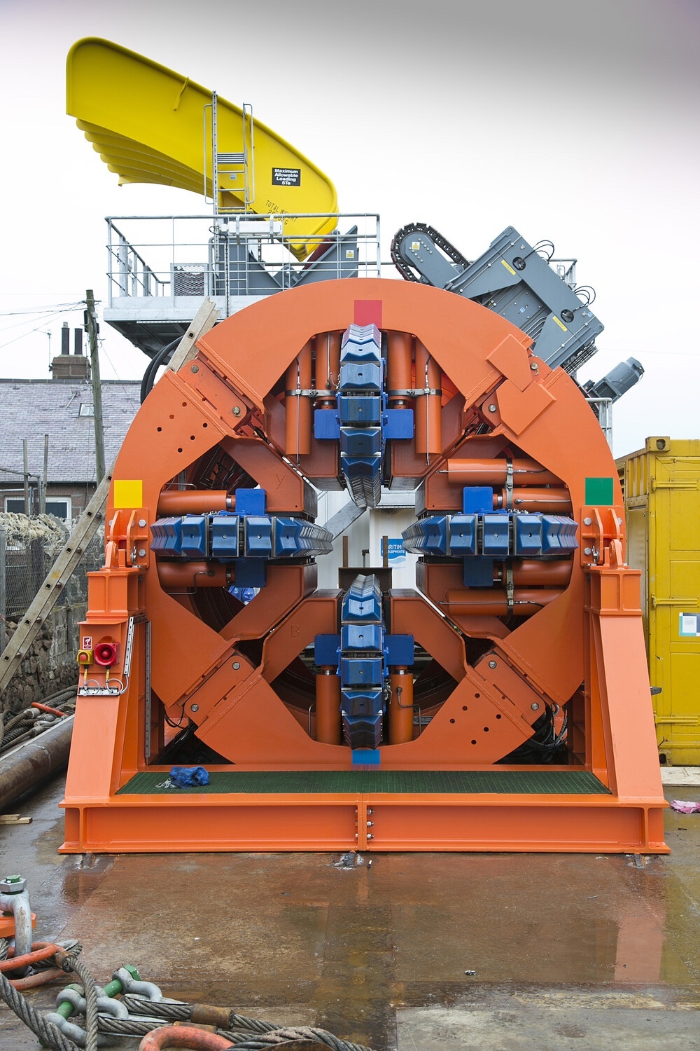
Our range also features the longest track contact length among available tensioners per single unit. The benefit of a longer track length is that a higher line-pull can be maintained by applying less squeeze to the product, as the squeeze load is spread over a larger area. This is particularly beneficial for products with low allowable squeeze.
Additionally, the track carriages are mounted on kingpins, allowing the tracks to pivot and adapt to product diameter transitions. This feature ensures a consistent grip throughout diameter changes, maintaining operational integrity.
There is a range of other features that optimise handling, including the self-centring alignment, all controlled through MDL’s state-of-the-art PLC systems and software developed in-house.
The technical capability that enables us to deliver such high standard equipment comes from first-hand experience of carrying out flexible lay and retrieval operations in harsh conditions – that is why you know the MDL technology truly is built for purpose.
That expertise is also at hand to analyse each flex-lay scope that comes our way; knowing our equipment range intimately we can perform the required calculations to specify the right tools for your cable (and mooring lines to save time!). To learn more on how we do that, look back at this Flex-lay Myths issue, where we disperse common tensioner myths.
Deploying Deeper
The MDL tensioner-driven packages become even more relevant as we are looking into the crystal ball of what the redesigned cables of tomorrow may look like – providing a future-proofing reassurance for ambitious FOW players, today.
According to the Clarksons’ report, increases in generating capacity will lead to a requirement for increased cable sizes – albeit they will not need to increase proportionally to the wind turbine (WTG) capacity. However, with the increase in voltage (initially transition from 33kV to 66kV, and now, transition from 66kV to 132kV), some increase to the size of the conductor is likely.
The physical forces of deeper waters call for higher line tensions, but the delicate composition of the product is likely to require less squeeze than traditionally experienced with SURF. The longer track contact length becomes imperative to strike this balance – but with traditional approaches on the market, that would require deploying multiples of cable handling equipment in-line.
While that approach delivers the track contact length, it also increases the risk from any of the individual systems failing and reducing the entire spread’s line pull capacity to maintain safe (and optimised) hold of the product.
Thankfully, MDL’s single-unit tensioner range is hugely powerful – up to 162-tonne line pull from a single unit – which gives it a lot of backup power without relying on additional equipment; and with the Failsafe Grip System ready to kick in, in the event of critical failure in the vessel network.
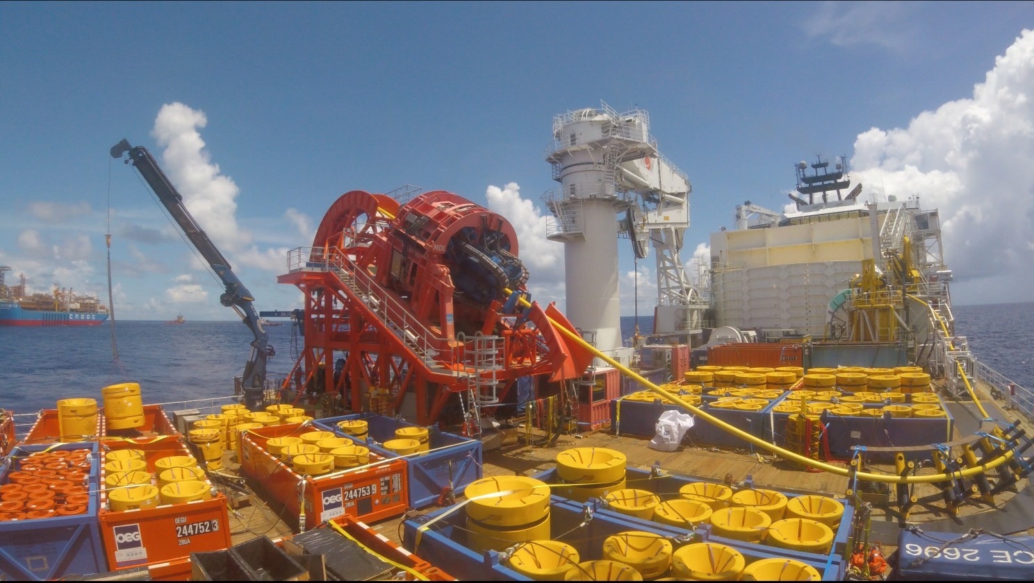
The added benefit of the MDL solution is the smaller footprint, which means it can be easily deployed on a VLS or HLS for the most optimal installation angles for the sea-state conditions. Our compact packages help with maximising the vessel back deck space, allowing you to carry more of the cable, buoyancy modules or ancillary equipment on board, to reduce the need for repeat trips to port. Check out this project offshore China as an example.
As is the case with all MDL equipment, the beauty lies in its versatility to be deployed off any available vessel with a crane; this flexibility gains an even deeper meaning with offshore wind developments, where the GHG burden of the construction is under high scrutiny, driving for the most responsible approaches. One such approach is sourcing a vessel available locally and converting it into a cable layer for only as long as it is needed, in place of bringing a construction vessel from overseas.
All this means an optimised cable installation, with the safest flexibles’ handling technology on the market, while reducing the carbon footprint of the operation. Product protected – and no compromises!
The all-important cherry on top
What comes with the increasing water depth and therefore length of cables is the need for them to float - aka the dynamic element, which will be facilitated by multiples of buoyancy modules. To put things into perspective: a study by OREC in 2021 identified that a sample 500MW floating windfarm would require between 578-861 buoyancy modules.
Today, installation of these is a highly manual process, which can take from 30min per module on a good day (when offshore conditions allow safe personnel working). MDL has identified that is one of the areas where time could be saved, not just to preserve the budget, but – more importantly - to safeguard the schedule, helping to further improve the chances of bringing power to the grid on time. We are building innovation to automate the buoyancy installation process, resulting in a smooth execution, with minimal to no manual handling in sight – but for that, you will have to speak to our team directly. We can’t give away all our trade secrets...!
Before you head offshore
But, of course, cable handling is not limited to overboarding offshore – the process of putting a flexible under some level of stress starts on the quayside or at the manufacturer’s facility, when proverbial and literal wheels are put in motion, moving the cable from production to temporary storage and into the installation package. We have already covered the different storage options in our last newsletter; in our next issue we will continue the thread, by exploring what it takes beyond equipment to preserve flexibles’ integrity before they begin their life subsea.
When in doubt #TrusttheExperts. Our track record of experience and expertise in cable lay solutions in the oil and gas sector puts us in the ideal position to be the solution engineers in offshore wind.
Get in touch to explore how we can make it one of your success stories too.
- April 2024MDL supports Saipem on Greece INGS
- January 2024Preparation is key to a long life subsea
- January 2024Forward thinking with Holland
- January 2024Ensuring peak performance for FPSO and platform owners in 2024
- December 2023Reducing the risk of cable failures


