Flex-lay Myths: Tensioner capabilities - part 2
- Share this story


Here are all the tools you need for identifying your ideal tensioner enabler.
How to spec a Tensioner System for your scope
As mentioned in our previous blog on tensioner capabilities, there’s no “one-size-fits-all” in the world of flex lay and each scope requires careful consideration to identify the most appropriate system for safe and efficient operations – but that certainly doesn’t mean opting for overkill.
We will be looking for the optimum handling solution to ensure the integrity is preserved, while keeping the job on schedule and on budget - time to get technical.

There are several critical factors that must be considered to determine the suitability of a tensioner system for your mission.
Product Factors – Determined by Manufacturer
1. Maximum Tensile Load (Te)
Simply the maximum tension that the product can safely sustain. This value will be variable depending on bend radius being applied and whether the product is in storage, installation or operational.
2. Product’s internal and external coefficient of friction (µ)
The internal coefficient of friction of a product quantifies the tendency of its internal layers to slide against each other. The external coefficient of friction refers to the ease at which the outer surface slips when in contact with another surface.
3. Maximum permissible squeeze (Te/m/track)
The squeeze that can be applied to a product will vary depending on:
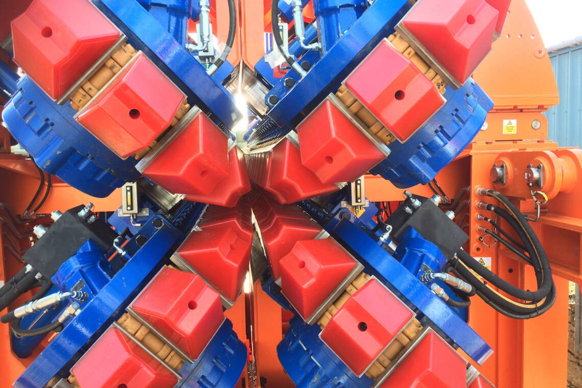
- Tensioner pad angle – Typically a pad angle <150° is deemed ‘v’ shaped and ≥150° is deemed ‘flat’
- Number of tensioner tracks – Products will generally have a lower permissible squeeze value in a 2-track tensioner acting in either horizontal or vertical than a 4-track tensioner operating in both planes.
The maximum permissible squeeze ensures that the product integrity is not compromised, while the minimum squeeze prevents product slip.
Operational Factor
Maximum anticipated line pull
It is critical to ensure that the maximum calculated line pull, inclusive of dynamic factors, does not exceed the product manufacturer’s stipulated maximum installation tension. In addition, even when installing products, calculating the maximum anticipated line pull must allow for recovery loads inclusive of the capstan effect we spoke about in our previous blog.
Armed with answers to the above, an optimal tensioner system can be selected that ensures safe and efficient execution.

Test study: A “50-tonne” tensioner
Let’s assume that for your product installation you have determined a 46-tonne maximum line pull is required. A 50-tonne tensioner will be more than capable to handle that, as far as line pull goes.
Next, you need to consider the allowable squeeze - let’s assume the product’s maximum permissible squeeze is 44Te/m/track.
This is the force exerted by the tensioner’s tracks in order to keep the product firmly in place when in standby, or moving in the desired direction when operational.
To identify if a tensioner system is suitable, we need to look at the product’s Coefficient of Friction - the CoF – stated by the product manufacturer - and confirm that it aligns with the tensioner’s line pull at that CoF.
Once we divide the line pull by the coefficient of friction, we will determine the minimum overall squeeze required to secure the product. A plausible CoF is 0.07. So, in our example, the 46-tonne line pull will require a total squeeze of 657-tonne to achieve 46Te line pull.
This total squeeze is then divided between the number of tracks that will be deployed - typically you will be looking at a 2- or 4-track operation. This will give us the minimum squeeze value per track.
For our example tensioner, that is either 328.5-tonne per track in a 2-track mode; or 164.3-tonne in a 4-track mode.
To determine the minimum contact length of the tensioner track we divide the 164.3 by the 46Te line pull which gives a length of 3.6m track length.
However, only select tensioners on the market have a contact length greater than 3.5m - and so it transpires that not all 50Te tensioners are the same.

One possible workaround is a dual tensioner system to double up on your line pull, and therefore squeeze capability. The risk with that option, however, is that if one of these systems fails, your squeeze will be reduced to below the required capability, with potential for product slippage.
Alternatively, you can opt for one of MDL’s 50Te Tensioner Systems – still portable, road transportable and setting the bar for safety on the tensioner market – but much more capable (featuring 4m track contact length, among others factors).
MDL offers single tensioner systems up to 162Te Maximum line pull and can achieve up to 90Te/m/track squeeze – making our range the most capable single unit systems on the market.
As stand-alone units, they carry the same efficiencies as our patented 50-tonne system - and can be used as part of a (W)HLS for installations up to 150-tonne line pull - without the requirement for a VLS vessel.

This example shown above perfectly demonstrates why MDL range is a market leader: from setting a gold standard in operational safety through their specialist design features, to offering increased capability with fewer systems – translating into lower overall costs in terms of minimum deck space, mobilisation, sea-fastening and personnel requirements.
Hopefully, you now have a much better understanding of the differentiators between tensioners and why choosing one for your project is not as simple as solely looking at the line pull.
If in doubt, just call. Our in-house team of engineers and experienced project managers is on hand to perform the required calculations for you, to identify the best solution for your lay or retrieval scope – giving you the peace of mind that you won’t be left short-changed on your critical projects.
- April 2024MDL supports Saipem on Greece INGS
- January 2024Preparation is key to a long life subsea
- January 2024Forward thinking with Holland
- January 2024Ensuring peak performance for FPSO and platform owners in 2024
- December 2023Reducing the risk of cable failures


